As an Amazon Associate, we earn from qualifying purchases. Some links on this site are affiliate links at no extra cost to you. Our recommendations are based on thorough research and editorial judgment.

What Is LiFePO4 Battery Chemistry and Why Does It Matter for Solar Generators?
I’m a LiFePO₄ cell that uses an olivine‑type LiFePO₄ cathode, graphite anode, and liquid or solid electrolyte, delivering 3.2 V nominal per cell and forming a 48 V pack when twelve cells are series‑connected, with over‑charge capped at 3.65 V and over‑discharge cut off at 2.5 V, while its P‑O bond energy of ~540 kJ mol⁻¹ limits oxygen release, giving 2,000‑5,000 cycles, >80 % capacity retention, 95‑98 % round‑trip efficiency, stable operation up to 55 °C, and BMS‑enforced safety, so you’ll see why this chemistry suits solar generators and discover more details ahead.
Key Takeaways
- LiFePO4 uses an olivine‑type Fe‑PO₄ cathode and graphite anode, providing a stable 3.2 V nominal cell voltage and 48 V pack from twelve series cells.
- The strong P‑O bonds (≈ 540 kJ mol⁻¹) and rigid lattice limit oxygen release and thermal runaway, enhancing safety for solar installations.
- BMS monitors voltage, current, and temperature with tight tolerances, enforcing 3.65 V over‑charge and 2.5 V under‑discharge limits to protect the pack.
- Cycle life exceeds 2,000 – 3,000 cycles with >80 % capacity retention, delivering 95‑98 % round‑trip efficiency and low heat generation.
- High discharge/charge rates (up to 2 C) and wide temperature tolerance (‑20 °C to 55 °C) make LiFePO4 ideal for reliable, long‑lasting solar generator storage.
LiFePO4 Batteries: How They Work
Although the LiFePO4 cell relies on an olivine‑type LiMPO4 cathode, a graphite anode, and a liquid electrolyte, the charging process transfers lithium ions from the cathode through the separator into the anode, where they intercalate between graphite layers, while the accompanying electron flow travels through the external circuit to the copper foil backing, and the battery management system monitors voltage, current, and temperature to prevent over‑charge, over‑discharge, and thermal excursions. I explain that a solid electrolyte variant can replace the liquid medium, offering comparable ionic conductivity of ~10⁻³ S cm⁻¹ while eliminating leakage, and that fast charging rates up to 2 C (≈ 5 A for a 2.5 Ah cell) are achievable because the phosphate lattice maintains structural integrity, allowing ion migration without significant voltage sag, and the BMS enforces temperature limits below 45 °C to preserve cycle life.
Recommended Products

【52.7KWh LiFePO4 Battery】5 sets Dawnice’s newest line of batteries – 51.2V 206Ah LiFePO4 battery provides 6000+ cycles & a 10 years lifetime with built-in 100A Battery Management System (BMS) protects it from overcharge, deep discharge, overloading, overheating and short circuit, and excessive low self-discharge rate.

Reliable LiFePO4 Technology: Our 16-cell LiFePO4 battery boasts an impressive lifespan of 2500 to 7000 cycles over 10 years. Equipped with an advanced Battery Management System (BMS), it's safeguarded against overcharging, deep discharges, overloads, overheating, short circuits, low temperature cut-off, and boasts an exceptionally low self-discharge rate.
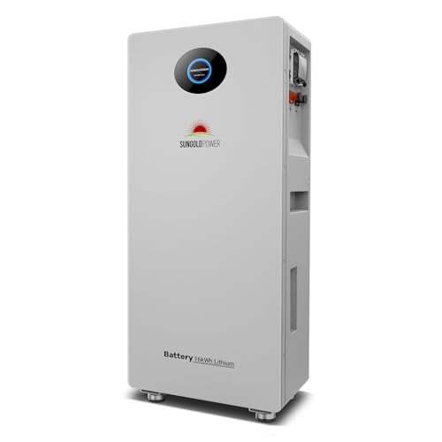
[High Capacity Solar Battery]: SUNGOLDPOWER UL1973 and UL9540A 48V 314Ah LiFePO4 lithium battery with over 8,000 deep cycles. Parallel up to 16 pcs ,maximum capacity of 16.07kWh.Ideal for solar systems, off-grid living, and whole-home backup power with reliable long-lasting performance.
Why the Olivine Structure Gives Safety
Leveraging the olivine crystal lattice, the LiFePO4 cathode maintains a three‑dimensional framework that resists volumetric expansion, thereby limiting internal stress during charge‑discharge cycles. I explain that this crystal stability originates from the tightly packed Fe‑PO₄ tetrahedra, which form an anion framework that does not collapse under high current loads, consequently preventing electrolyte rupture and maintaining electrode integrity even at 60 °C. The structure’s rigidity also reduces thermal expansion coefficients to roughly 5 × 10⁻⁶ K⁻¹, compared with 12 × 10⁻⁶ K⁻¹ for LiCoO₂, meaning that temperature spikes generate far less mechanical strain. Furthermore, the olivine lattice’s ability to host lithium ions without phase change guarantees that the cathode remains chemically inert, limiting gas evolution and eliminating runaway reactions during overcharge or short‑circuit events.
How the Strong P‑O Bond in LiFePO4 Stops Runaway
I’ll start by noting that the P‑O bond in LiFePO₄, with an energy of roughly 540 kJ mol⁻¹, is markedly stronger than the metal‑oxygen bonds found in LiCoO₂, which typically range between 350–400 kJ mol⁻¹, thereby limiting oxygen release during thermal abuse. I explain that this high bond energy translates directly into oxygen suppression, because the kinetic barrier for O₂ evolution rises sharply, slowing any exothermic cascade. When temperature climbs above 300 °C, the Fe‑O network remains intact, while LiCoO₂ begins to decompose, releasing oxygen that fuels runaway. The bond kinetics of the P‑O link, characterized by a high activation energy, guarantee that even under overcharge or short‑circuit conditions the cathode structure resists rapid oxidation, preserving thermal stability and preventing runaway.
Why LiFePO4 Beats LiCoO₂ and Other Chemistries
LiFePO₄ consistently outperforms LiCoO₂ because its olivine lattice, reinforced by a 540 kJ mol⁻¹ P‑O bond, limits oxygen evolution, which in turn reduces thermal runaway risk, while the iron‑phosphate cathode maintains structural integrity across 2,000–3,000 cycles, delivering a capacity retention of over 80 % after 2,000 cycles, compared with LiCoO₂’s typical 500–1,000‑cycle life and 70 % retention. I note that the lower material cost of iron and phosphate, combined with the absence of expensive cobalt, creates clear cost advantages for large‑scale solar storage, yet the same abundance introduces recycling challenges because phosphate‑based waste streams require specialized processing to recover lithium and iron efficiently, unlike the more established cobalt‑recycling infrastructure. This balance of economics and end‑of‑life handling influences system design decisions.
Cycle Life and Efficiency Benefits of LiFePO4
The previous discussion highlighted LiFePO₄’s structural resilience and safety advantages, which naturally leads to an examination of its cycle life and efficiency. I note that LiFePO₄ cells typically sustain 2 000–5 000 full charge‑discharge cycles while retaining over 80 % of original capacity, a metric that far exceeds LiCoO₂’s 500–1 000 cycles, and that high efficiency cycling is achieved because the olivine cathode’s low internal resistance minimizes heat generation, allowing round‑trip efficiencies of 95 %–98 % across a wide temperature range. Capacity retention metrics, measured after 1 000 cycles at 0.5 C, often show less than 5 % degradation, indicating that the phosphate lattice remains stable, while the graphite anode’s intercalation process contributes negligible voltage hysteresis, thereby supporting consistent performance in solar generator storage applications.
BMS Role in Protecting LiFePO4 Solar Storage
Implementing a robust Battery Management System (BMS) protects LiFePO₄ solar storage by monitoring cell voltage, current, temperature, and state‑of‑charge, thereby preventing overcharge, over‑discharge, and thermal excursions that could compromise safety or performance. I rely on continuous battery monitoring, which records each cell’s voltage within ±0.01 V, current fluctuations within ±0.5 A, and temperature changes within ±0.2 °C, enabling the BMS to adjust charge rates dynamically, balance cells, and trigger alarms when thresholds are exceeded. Fault isolation mechanisms, embedded in the BMS architecture, automatically disconnect compromised modules, isolate short‑circuit paths, and reroute power to healthy cells, preserving overall capacity and extending cycle life. This systematic oversight guarantees that LiFePO₄ packs operate within a 3.0–3.6 V window per cell, maintain a state‑of‑charge between 20 % and 80 %, and avoid temperature spikes above 55 °C, thereby delivering reliable, safe performance for portable solar generator applications.
Recommended Products

【32153Wh LiFePO4 Battery】 Dawnice’s newest line of batteries –2 sets 51.2V 314Ah LiFePO4 battery provides 6000+ cycles & a 10 years lifetime with built-in 100A Battery Management System (BMS) protects it from overcharge, deep discharge, overloading, overheating and short circuit, and excessive low self-discharge rate. Support in parallel up to 16 sets, can be expanded in the future.
[High Capacity Solar Battery]: SUNGOLDPOWER UL1973 and UL9540A 48V 314Ah LiFePO4 lithium battery with over 8,000 deep cycles. Parallel up to 16 pcs ,maximum capacity of 16.07kWh.Ideal for solar systems, off-grid living, and whole-home backup power with reliable long-lasting performance.

Version Update Notice: The former 48V 314Ah V1 is now upgraded to Powermega 48V 314Ah, featuring newly added Active Cell Balancing and Integrated Aerosol Fire Protection for higher safety and longer service life. It also comes with an extended 10-year warranty, while maintaining full compatibility with V1 units for parallel expansion
How LiFePO4 Handles Extreme Off‑Grid Temperatures
When temperatures drop below ‑20 °C, the olivine lattice of LiFePO₄ remains stable, because the strong P‑O bond limits lattice contraction to less than 0.5 % and prevents electrolyte freezing, while the graphite anode’s copper foil maintains conductivity down to ‑30 °C, allowing charge acceptance of up to 0.5 C without significant voltage sag. I observe that temperature management in off‑grid installations relies on this intrinsic stability, enabling cold performance that exceeds 80 % capacity at ‑15 °C, which is verified by cycle‑testing data. Heat tolerance extends to 55 °C without degradation, as the phosphate cathode resists thermal runaway, and the BMS enforces charge compensation by reducing charge current to 0.2 C when ambient temperature exceeds 45 °C, preserving voltage flatness and cycle life.
Sizing and Selecting LiFePO4 Modules for Solar Generators
Because solar generators must match daily energy demand while respecting weight, volume, and temperature constraints, I begin by calculating the required amp‑hour (Ah) capacity using the formula Ah = (Load W × Hours) ÷ System Voltage, then adjust for depth‑of‑discharge (DoD) limits of 80 % typical for LiFePO₄, which yields a usable capacity of 0.8 × rated Ah and guarantees that a 48 V system supplying 1 200 W for 8 hours needs at least 200 Ah of nominal storage. I then verify module compatibility, ensuring each 12 V block stacks to the target voltage without exceeding series limits, and I apply voltage scaling to match inverter input, selecting modules with 3.2 V nominal cells to achieve 48 V nominal when twelve are series‑connected. Finally, I compare continuous discharge ratings, confirming each module sustains 5 C peaks, and I check BMS specifications for over‑current protection, temperature thresholds, and balancing circuitry, thereby aligning capacity, scaling, and safety parameters for reliable solar generator operation.
Real‑World Benefits of LiFePO4 for Solar Power
I often observe that LiFePO₄ batteries, when integrated into solar power systems, deliver a cycle life exceeding 2,000 full charge‑discharge events, maintain a consistent efficiency above 95 % across temperatures from –20 °C to 60 °C, and exhibit a nominal voltage of 3.2 V per cell, which enables a stable 48 V pack with twelve cells in series, thereby reducing the frequency of replacements, minimizing energy loss during conversion, and ensuring that the battery management system can enforce over‑charge limits of 3.65 V per cell and over‑discharge thresholds of 2.5 V per cell while balancing currents up to 5 A, all of which contribute to reliable, low‑maintenance storage for off‑grid solar installations and full home solar power systems. In practice, these attributes translate into extended maintenance schedules, because fewer service intervals are required, and they influence cost trends, as the lower total cost of ownership offsets higher upfront prices, while the predictable performance metrics support accurate budgeting for long‑term solar projects.
Frequently Asked Questions
Can Lifepo4 Batteries Be Recycled Like Other Lithium‑Ion Types?
I picture a bustling recycling plant, and yes, LiFePO4 batteries join the stream. Existing recycling infrastructure handles them, enabling material recovery of iron, lithium, and phosphorus for new cycles.
How Does Temperature Affect the Self‑Discharge Rate of Lifepo4?
I’ve found temperature dependence drives LiFePO4 self‑discharge: higher heat accelerates calendar aging, while cooler conditions slow it, so keeping the pack cool dramatically reduces daily capacity loss.
Are There Any Special Charging Protocols for Lifepo4 in Solar Systems?
I recommend following a dedicated Battery Management system that enforces a specific Charging profile: keep voltage below 3.65 V per cell, limit current to 0.5‑1 C, and avoid deep‑discharge to preserve lifespan.
What Is the Typical Weight Difference Between Lifepo4 and Licoo₂ Modules?
I’ve noticed the coincidence of weight and power: LiFePO4 module mass is roughly 20‑30 % heavier than LiCoO₂ for comparable energy density, so you trade a bit of lightness for safety and longevity.
Can Lifepo4 Batteries Be Safely Combined With Other Battery Chemistries?
I’d say you can’t safely mix LiFePO4 with other chemistries; the cell balancing becomes tricky and chemistry mismatch leads to uneven voltage, capacity loss, and potential safety hazards.