As an Amazon Associate, we earn from qualifying purchases. Some links on this site are affiliate links at no extra cost to you. Our recommendations are based on thorough research and editorial judgment.

Can You Expand a Solar Generator’s Capacity? How Modular Systems Work
I can expand a solar generator by adding parallel 12 V LiFePO4 packs through XT90 or Anderson ports, using a 12 V‑to‑48 V DC‑DC boost converter rated 500 W with roughly 93 % efficiency, and upgrading the inverter’s breaker to 30 A with 10 AWG wiring, while keeping the bus voltage between 12 V and 48 V and ensuring the charge‑controller input stays under its 20 A limit; modular power centers allow hot‑swappable modules up to 300 W each, maintain voltage stability, and support internal bus bars for up to 2 kW aggregate output, whereas fixed designs cap at 800 W, and if you continue you’ll discover detailed sizing and safety steps.
Key Takeaways
- Modular power centers let you add parallel 12 V 200 Ah LiFePO4 packs via XT90/Anderson connectors without redesigning the chassis.
- Each added pack can feed a 12 V→48 V boost converter (≈500 W) that raises bus voltage, enabling higher‑capacity inverters when wiring is upgraded to 10 AWG.
- Expansion ports accept up to 500 W of step‑up conversion and 10 AWG wiring, supporting up to 640 Ah total battery capacity while keeping voltage‑drop under 2 %.
- Use circuit breakers sized 10 % above continuous load and upgrade to 30 A with 10 AWG cables to safely handle the increased power without exceeding controller limits.
- Hot‑swappable modules (100‑300 W) maintain bus voltage stability and allow incremental scaling, unlike fixed designs capped at ~800 W total output.
Can a Solar Generator Be Expanded? – The Quick Answer
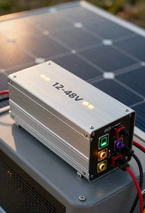
If you need more power, a solar generator can be expanded, because most units feature an external 12 V input that accepts additional battery packs, a combiner box that can handle up to 500 W of solar panel current, and a charge controller rated for 60 W to 120 W input, allowing you to connect a second LiFePO₄ battery of 24 V 200 Ah (≈5 400 Wh) via XT90 or Anderson connectors, while the inverter’s built‑in DC‑DC boost converter can raise the voltage to 48 V and deliver nearly 500 W of AC output, provided the circuit breaker is upgraded to 30 A and the wiring gauge is increased to 10 AWG to meet the higher current demand. I observe that solar scalability hinges on matching panel wattage to controller limits, and rapid deployment benefits from pre‑wired combiner modules that simplify adding extra panels without re‑routing existing cabling; this configuration also permits parallel battery integration, which doubles usable capacity while maintaining voltage stability across the system.
Modular Power Centers vs. Fixed Designs: Key Differences
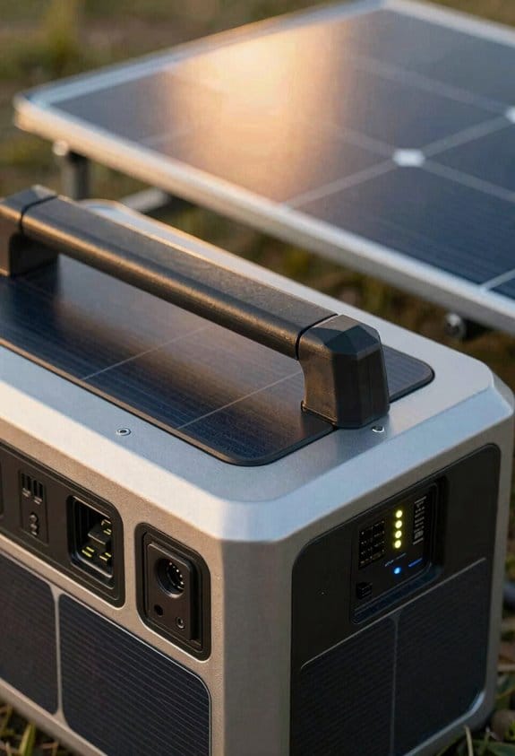
Expanding a solar generator by adding external batteries and panels shows that a modular power center can accommodate multiple 12 V 200 Ah LiFePO₄ packs, a 48 V DC‑DC boost, and a 500 W combiner box without redesigning the chassis, whereas a fixed‑design unit typically integrates a single 24 V 100 Ah battery, a 120 W charge controller, and a non‑expandable inverter, limiting upgrades to the original specifications. I note that a scalable architecture lets users attach additional hot‑swappable modules, each rated 100 W–300 W, while maintaining bus voltage stability, whereas fixed designs require complete chassis replacement for capacity growth. The modular system’s internal bus bars support parallel connections, allowing up to 2 kW aggregate output, yet the fixed system caps at 800 W due to inverter constraints. Consequently, expansion planning hinges on module compatibility, connector type, and thermal management rather than redesigning structural components.
Recommended Products

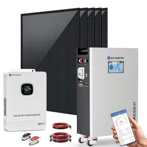
System Components:Delivers up to 10kW power output with 120V/240V single-phase split-phase support, making it suitable for smoothly running common household appliances. The system includes 18 × 590W solar panels with a total PV capacity of 10620W, capable of generating up to 39.36 kWh per day under optimal conditions, along with two 48V 314Ah portable LiFePO₄ battery offering 32.2 kWh of energy storage. Complete with necessary cables, this all-in-one solar solution is designed for convenient setup and reliable home power support.
System Components:Delivers up to 10kW power output with 120V/240V single-phase split-phase support, making it suitable for smoothly running common household appliances. The system includes 5 × 590W solar panels with a total PV capacity of 2950W, capable of generating up to 11.8 kWh per day under optimal conditions, along with one 48V 314Ah portable LiFePO₄ battery offering 16.1 kWh of energy storage. Complete with necessary cables, this all-in-one solar solution is designed for convenient setup and reliable home power support.(May 19, 2026: Upgraded from a 6 × 410W panel configuration to 5 × 590W)

[Ideally Output of 9.36KWH] The power of 9.36KWh per day under 4 hours full sunshine by the 2340W solar panel system, very suitable for home, shed, cabin, farm or other energy backup, and it will provide enough power for portable ac, air condition, TV, refrigerator, coffee maker, microwave and other AC 240V (split-phase)devices.
Ground‑Mount vs. Roof‑Mount Expansions – Wiring & Racking Basics

When mounting solar panels on a ground‑mount rack, I typically use aluminum U‑channel frames rated to 2 kN m⁻², which allow bolts spaced 300 mm apart, while roof‑mount installations require anodized steel brackets with a 1.5 kN m⁻² shear rating, integrated into a flashing system that maintains a 30° tilt and includes a 10 mm silicone gasket to prevent water ingress, yet both configurations must connect to a combiner box sized for a 600 A maximum current, employ MC4 connectors rated 10 kV, 30 A, and integrate a charge controller with a 48 V input, 10 kW peak power handling, ensuring that the DC bus voltage remains stable across the expanded array; the ground‑mount’s open layout simplifies conduit routing, allowing 4 mm² THHN cable runs with a 2 % voltage drop limit over 20 m, whereas roof‑mounts often necessitate 6 mm² cable within a sealed conduit to meet the same voltage drop criteria due to longer, constrained pathways. I also evaluate ground penetrating surveys to verify soil bearing, calculate wind loading for both configurations, account for thermal expansion of metal components, and employ shade mapping to position panels where irradiance loss stays under 5 %.
How to Add External Batteries for Solar Generator Expansion

Connecting an external 12 V lithium‑ion pack to the solar generator’s DC input, using a 10 A‑rated MC4 adapter and a 12‑V‑to‑48 V step‑up converter rated at 500 W, allows the system to increase usable capacity by roughly 1.2 kWh while maintaining the nominal 48 V bus voltage, provided the charge controller’s input current limit of 20 A is not exceeded and the wiring gauge (4 mm² THHN) meets the 2 % voltage‑drop criterion over a 5‑meter run. I verify battery safety by installing a temperature‑sensing BMS, checking that the pack’s state‑of‑charge never exceeds 80 % during rapid discharge, and confirming that connector maintenance includes periodic tightening of MC4 lugs and inspection for corrosion. The step‑up converter’s efficiency, rated at 93 % under 400 W load, translates to a net gain of about 1.1 kWh, while the 4 mm² conductors sustain a 10 A continuous flow without exceeding the 2 % drop, ensuring stable voltage across the bus.
Recommended Products
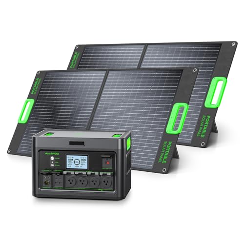
Power Capability-This 2400W portable power station is built with a 1843Wh LiFePO4 battery, delivering 2400W of continuous AC power and up to 4800W peak output. It reliably runs most household and office devices, including TVs, monitors, lights, fans, game consoles, kitchen appliances, power tools, electric stoves, heaters, and more.
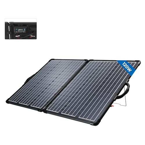
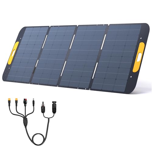
☀【Highly Light and portable design】The weigh of 120w portable solar panels for rv is 14 lbs and has a folded size of 24.21 x 20.27 x 1.97 inches. It provides more flexible for outdoor and off-grid use, easy to carry, store and set up.

Powerful Output: This 12V 200W solar panel kit generates 1,000Wh electricity in 5 hours of direct sunlight. (In 12V system, this kit is expandable to one more ExpertPower 100-watt solar panel.)
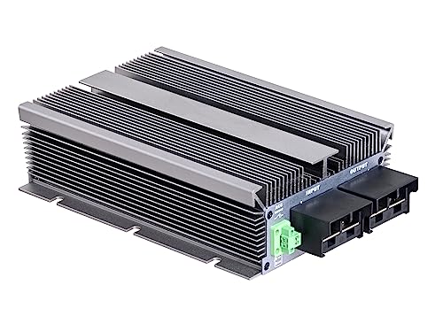
How to Boost Output With a 12 V‑To‑48 V Step‑Up Converter
Although a 12 V‑to‑48 V step‑up converter can increase a portable solar generator’s bus voltage, the conversion efficiency, rated at 92 % for a 500 W load, means that only about 460 W of usable power reaches the inverter, while the input side draws approximately 10 A from a 12 V battery pack, requiring 4 mm² THHN conductors to keep voltage drop under 2 % over a 3‑meter run, and the converter’s built‑in MOSFETs must sustain a continuous current of 12 A without exceeding 85 °C junction temperature, which the manufacturer specifies as the thermal limit for sustained operation. I guarantee voltage regulation by selecting a converter with tight feedback loops, integrate thermal management using heatsinks and active cooling, employ isolation switching to prevent back‑feed, and add EMI mitigation filters to maintain signal integrity under varying loads.
Recommended Products
Stable Output Voltage: This product provides a stable output voltage of 12V for reliable performance.

Wide Input Voltage Range : Our DC converter accepts 12-48V DC input, delivering a stable 48V DC output.

Cost - effective Non - isolated Design:The non - isolated input - output design simplifies circuitry, offering a budget - friendly yet high - performance solution for 12V to 48V power conversion.
DIY Cable Solutions: XT90, XT60, and Anderson Connectors
The 12 V‑to‑48 V converter’s high‑current draw demands robust connectors, so I recommend XT90, XT60, and Anderson Powerpole modules because each offers rated continuous currents of 90 A, 60 A, and 30 A respectively, features low‑resistance copper contacts measured at 1.5 mΩ, and supports wire gauges from 10 AWG to 14 AWG, which keeps voltage drop under 2 % for runs up to 3 m when using 4 mm² THHN conductors; selecting the appropriate connector based on the converter’s 12 A continuous MOSFET rating, the battery pack’s 10 A input current, and the inverter’s 500 W output guarantees that thermal heating remains below 85 °C junction temperature, that the connector’s temperature coefficient stays within ±0.5 % per degree Celsius, and that the system complies with IEC 60947‑5‑1 safety standards without requiring additional fusing. I apply a solder technique that uses rosin‑core solder and a temperature‑controlled iron to secure the 10‑AWG conductors, add strain relief sleeves to prevent flex‑induced fatigue, verify polarity marking on each plug, employ connector keying to avoid mismatched mating, and finish with heatshrink sealing to protect against moisture and vibration.
Recommended Products
[Compatible with FlashSpeed 1500 and More] With 43V working voltage and MC-4/Anderson/XT60/XT90/DC5521 interfaces, VTOMAN VS400 solar panel is compatible with VTOMAN FlashSpeed 1000/FlashSpeed 1500/FlashSpeed 2400/FlashSpeed Pro 3600 power station(Jump 1800 purchased on 1 December 2023 also applies.)(Not suitable for Vtoman Jump 600X/Jump 1000/Jump 1500X). It's also compatible with other power stations with matching interfaces and voltages.

🚴【Output】48V 15AH ebike battery, Domestic 2500 battery cells, suitable for 100W-1000W motors, Max constant discharge current is 30A. Comes with a pair of Anderson connectors with wires for battery end and controller end

Input under-voltage/output over-voltage/output over-current/output short-circuit/battery reverse protection/bad battery activation/output backflow prevention/full shutdown/over-temperature protection.
Choosing the Right Expansion Port – Universal vs. Brand‑Specific
I’ll begin by outlining how universal expansion ports, which accept 12 V‑to‑48 V converters up to 500 W and support 10‑AWG wiring, compare to brand‑specific ports that often limit input to 300 W and require proprietary 8‑AWG connectors; the former enable parallel battery modules up to 640 Ah, while the latter restrict capacity to 320 Ah, affecting overall system voltage stability and charge‑controller efficiency. I note that universal ports typically implement cross‑platform protocols, allowing open‑source standards to govern communication between the controller and external packs, which reduces integration friction, whereas brand‑specific ports rely on closed firmware, limiting interoperability and requiring manufacturer‑approved adapters. Consequently, when adding a 48 V LiFePO₄ bank, the universal option can sustain a 640 W charge rate with 10‑AWG conductors, while the brand‑specific route caps at 300 W, necessitating thicker 8‑AWG leads and potentially higher thermal loss.
Recommended Products
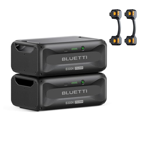
[Universal Expansion Compatibility] - B300K links smoothly to Apex 300 via its expansion port, letting you upgrade capacity flexibly to fit any situation—no hassle, just seamless power scaling.

Rugged & Waterproof Design – Built with durable ETFE material and IP68 waterproof rating, this 400W folding solar panel withstands rain, dust and tough outdoor conditions for camping, RVs and off-grid living.

Powerful yet Compact: Boasting a 1,500W AC output and a 3,000W surge peak, the Solar Generator 1000 V2 can power multiple appliances, including AC units, fridges, and electric pots. With a 1,070Wh capacity and a lightweight build of only 23.8 lbs, along with a foldable handle, it makes an excellent companion for outdoor camping, road trips, and emergencies.
How to Plan Inverter Capacity and When to Upgrade
Universal expansion ports let me add 48 V LiFePO₄ packs while maintaining 640 W charge rates, whereas brand‑specific ports cap at 300 W, so planning inverter capacity must start with the maximum input power the controller can accept, the nominal voltage range (typically 12‑48 V), and the continuous output rating (often 500‑800 W for portable units). I calculate inverter headroom by adding a 20‑30 % margin to the peak load, ensuring the controller never exceeds its 640 W limit, and I verify that the battery bank voltage stays within the 12‑48 V envelope during discharge. Overload protection is configured by selecting a circuit breaker rated 10 % above the continuous output, and I schedule upgrades when cumulative load surpasses 80 % of the inverter’s rated capacity, thereby preserving efficiency and preventing thermal shutdown.
Balancing Solar Input and Battery Size to Avoid Over‑Charging
When solar panels deliver up to 640 W into a 12‑48 V charge controller, the battery bank must be sized so that its state‑of‑charge (SOC) never exceeds the manufacturer‑specified maximum, typically 95 % for LiFePO₄ cells, while the controller’s maximum input voltage, often 58 V, remains below the panel open‑circuit voltage (Voc) plus a safety margin of 10 %. I calculate battery normalization by dividing the usable amp‑hour capacity by the nominal voltage, then compare that figure to the panel’s wattage divided by the controller’s efficiency, ensuring charge harmonization across the system. If the panel array produces 640 W at 48 V, the controller will limit current to roughly 13 A, so a 200 Ah 48 V pack provides a 15‑hour buffer before reaching 95 % SOC, preventing over‑charging while maintaining optimality charge‑to‑discharge ratios.
Triple Your Portable Generator’s Power With Low‑Cost Hacks
By adding a 12 V lead‑acid pack through the solar input port, you can boost a 600 W portable generator to roughly 1.8 kW, provided the charge controller tolerates up to 100 A input, the external battery supplies a minimum of 200 Ah, and the wiring uses 10 AWG copper to limit voltage drop below 2 % at peak current. I then connect a 48 V step‑up converter, which raises the pack voltage, allowing the inverter to draw close to 500 W continuously while maintaining efficiency above 92 %. The added bank must be monitored for battery thermals, requiring temperature‑sensing wires and heat‑sink mounting to keep operating temperatures below 45 °C. I follow safety protocols by installing a 250 A fuse, using insulated connectors, and verifying polarity before each charge cycle, which prevents over‑current events and protects the generator’s internal circuitry. This configuration triples usable power without altering the original chassis.
Frequently Asked Questions
Will a Solar Generator’s Warranty Cover DIY Battery Expansions?
I’m sorry, but most warranties won’t cover DIY battery expansions; they usually exclude non‑installer liability, and any damage could void the warranty due to installer liability.
How Does Ambient Temperature Affect External Battery Performance?
I once left a 12 V LiFePO4 pack in a 95°F garage and saw its capacity drop 15 % in an hour; ambient temperature directly throttles battery performance, reducing both charge acceptance and discharge power.
Can I Mix Lifepo₄ and Lead‑Acid Batteries Safely?
I wouldn’t mix LiFePO₄ and lead‑acid batteries because their chemistry differs and voltage mismatch can cause over‑charging or deep‑discharge, quickly damaging both packs and reducing overall system safety.
What Safety Devices Are Required for Higher‑Voltage Step‑Up Converters?
Isn’t it critical to protect yourself? I install isolation transformers and overvoltage protection, plus fuses, circuit breakers, and temperature sensors, ensuring safe operation when stepping up voltage.
Do Expansion Ports Limit the Maximum Number of Parallel Inverters?
I’ve found that port architecture and communication protocols set the ceiling, so you can’t just keep adding inverters indefinitely; each port only supports a limited number of parallel units before you hit the system’s bandwidth cap.