As an Amazon Associate, we earn from qualifying purchases. Some links on this site are affiliate links at no extra cost to you. Our recommendations are based on thorough research and editorial judgment.

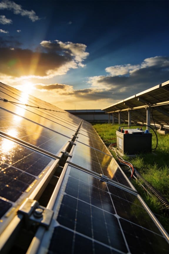
How Do Solar Panels Actually Work? A Plain-English Explanation

I explain that photons of about 1.1–3.5 eV strike silicon, lift electrons from the valence band to the conduction band, and create electron‑hole pairs, while the built‑in electric field of the p‑n junction, typically 0.6 V, separates these carriers, directing electrons to the N‑type side and holes to the P‑type side; metal contacts, usually silver‑tin alloy fingers with sheet resistance below 0.1 Ω/□, collect the carriers and channel them through low‑resistance bus bars and wiring, delivering roughly 0.5–0.7 V per cell and up to 8 A per module, which tempered glass and multilayer anti‑reflective coatings transmit over 92 % of the spectrum, and an inverter converts the DC to 120/240 V AC with 96–98 % efficiency, and further details await if you continue.
Key Takeaways
- Sunlight photons knock electrons loose from silicon atoms, creating electron‑hole pairs that become electric charge.
- The built‑in electric field at the p‑n junction separates these carriers, pushing electrons to the back and holes to the front of the cell.
- Metal contacts collect the separated carriers and send the resulting direct current through wiring to an inverter.
- Anti‑reflective glass and rear‑contact technologies maximize light absorption and carrier collection, boosting cell voltage and efficiency.
- Bypass diodes protect the system from shading, allowing current to flow around shaded cells and keeping the whole string operating.
Photon‑to‑Electricity Conversion in Solar Panels
When photons strike a silicon solar cell, their energy—typically ranging from 1.1 eV to 3.5 eV depending on wavelength—excites electrons from the valence band to the conduction band, creating electron‑hole pairs that the internal electric field at the p‑n junction promptly separates, directing electrons toward the N‑type side and holes toward the P‑type side. I then describe photon harvesting as the process by which absorbed photons generate carriers, noting that each 1 W cm⁻² of solar irradiance yields roughly 0.2 A cm⁻² of short‑circuit current under standard test conditions, while carrier recombination, both radiative and non‑radiative, reduces the quantum efficiency by up to 5 % in typical crystalline silicon cells, requiring surface passivation and bulk lifetime optimization to maintain conversion efficiencies above 20 % in commercial modules.
What the P‑N Junction Does Inside a Solar Cell
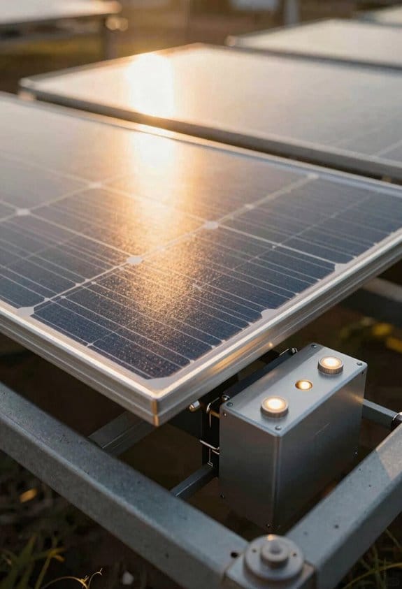
Because the p‑n junction establishes an internal electric field, it separates photogenerated electron‑hole pairs, driving electrons toward the n‑type region and holes toward the p‑type region, which creates a voltage of roughly 0.5–0.7 V per cell in modules used across portable solar panels and rooftop arrays under standard illumination. I explain that this field modulation, produced by the dopant concentration gradient, forms a depletion zone that blocks carrier diffusion, consequently preventing junction recombination, which would otherwise reduce open‑circuit voltage and fill factor. In practice, the built‑in potential, typically 0.6 V for crystalline silicon, is measured by a Kelvin probe, and the minority‑carrier lifetime, often 10–100 µs, indicates how efficiently the junction suppresses recombination. Consequently, the p‑n interface acts as a charge‑separator, enabling a stable forward bias when illuminated, while maintaining low reverse‑bias leakage currents, typically below 10⁻⁹ A cm⁻².
How Freed Electrons Generate Direct Current in a Panel
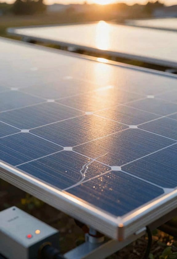
I’ll start by describing how the liberated electrons travel through the cell’s conductive pathways, creating a unidirectional flow that constitutes direct current; the electron motion is driven by the built‑in electric field at the p‑n junction, which pushes electrons toward the n‑type side while holes migrate to the p‑type side, and the metal contacts on the front and back of the panel collect these carriers, channeling them into external wiring that delivers the DC power to the inverter or charge controller, where typical silicon cells generate about 0.5–0.7 V per cell under standard test conditions, and a series‑connected string of 60 cells can consequently produce roughly 30–42 V, with the current limited by the lowest‑performing module in the string, commonly ranging from 5 A to 9 A for residential panels. This charge separation creates a voltage gradient that initiates electron drift across the semiconductor lattice, allowing continuous current flow when the circuit is closed, while the built‑in field maintains directionality, preventing recombination and ensuring that each photon‑induced carrier contributes to measurable power output.
How Metal Contacts and Wiring Gather the Power
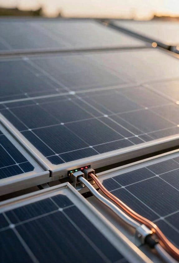
The liberated electrons, once directed by the p‑n junction’s internal field, encounter the front‑side grid of silver‑tin alloy fingers and the rear‑side bus bar, both of which are engineered to minimize resistive losses by employing low‑resistivity conductors with sheet resistance typically below 0.1 Ω/□. I then explain how metal contacts collect the current, noting that each finger is 5 µm wide, spaced 1 mm apart, and soldered to a copper bus bar with a resistance under 0.02 Ω, ensuring that the generated charge flows efficiently toward the panel’s output terminals. The wiring layout, designed as a series‑parallel network, links cells in strings, each string maintaining a voltage of roughly 0.6 V per cell, while parallel connections increase current up to 8 A per module, and the overall system resistance stays below 0.5 Ω, preserving power output and reducing thermal loss.
Tempered Glass and Anti‑Reflective Coatings for Solar Panels
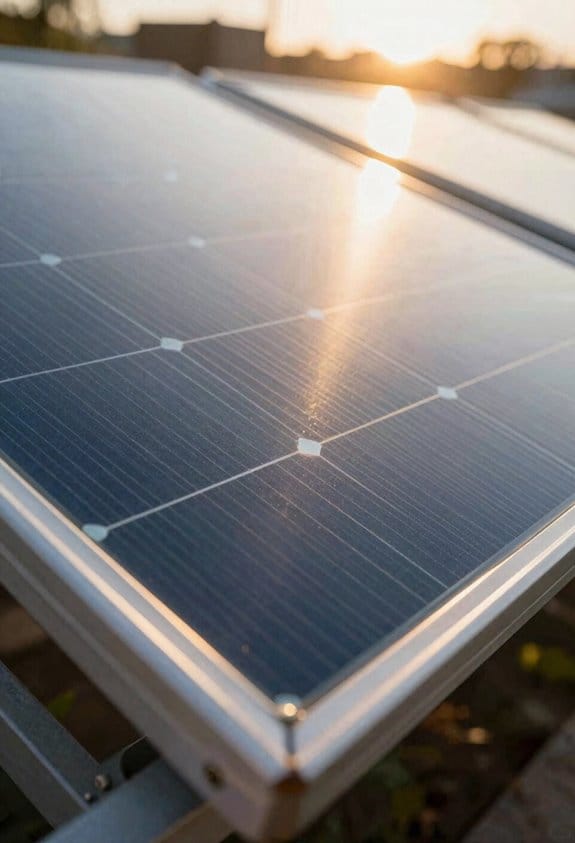
When sunlight strikes the panel, the tempered glass—typically 3 mm thick, low‑iron soda‑lime composition, and heat‑treated to achieve a break‑strength of 1.2 MPa—protects the cells while transmitting over 92 % of the solar spectrum, and the anti‑reflective coating, applied as a multilayer SiO₂/TiO₂ stack with a refractive index gradient, reduces surface reflectance from roughly 30 % to under 4 % across the 400–1100 nm wavelength range, thereby increasing photon absorption; I note that durability testing, which includes thermal cycling, impact resistance, and hail impact simulations, confirms that the glass maintains structural integrity after 25 years of exposure, while visual transparency remains above 92 % even after prolonged UV stress, ensuring consistent light delivery to the cells.
Recommended Products

Reliable LiFePO4 Technology: Our 16-cell LiFePO4 battery boasts an impressive lifespan of 2500 to 7000 cycles over 10 years. Equipped with an advanced Battery Management System (BMS), it's safeguarded against overcharging, deep discharges, overloads, overheating, short circuits, low temperature cut-off, and boasts an exceptionally low self-discharge rate.

【9.6KWh LiFePO4 Battery】 Dawnice’s newest line of batteries with UL– 48V 200Ah LiFePO4 battery provides 6000+ cycles & a 10 years lifetime with built-in 100A Battery Management System (BMS) protects it from overcharge, deep discharge, overloading, overheating and short circuit, and excessive low self-discharge rate.
[Bifacial Technology] Designed to capture sunlight from both sides, this panel increases energy yield by up to 30%, making it ideal for various installations, including rooftops and ground mounts.
Al‑Bsf, PERC, and TOPCON Rear‑Contact Technologies That Boost Efficiency
Boosting efficiency in both utility modules and home solar power systems, Al‑Bsf, PERC, and TOPCon rear‑contact technologies each modify the back surface of silicon cells to reduce recombination losses, increase carrier collection, and enhance light trapping; Al‑Bsf employs an aluminum back surface field that reflects unabsorbed photons, PERC adds a passivated emitter rear contact with a dielectric stack and localized rear contacts, while TOPCon integrates a tunnel oxide layer and a doped polysilicon contact, allowing carriers to tunnel through the oxide, thereby achieving measured efficiency gains of 1.5‑2.0 % for Al‑Bsf, 2.0‑2.5 % for PERC, and up to 3.0 % for TOPCon relative to baseline cells, with typical open‑circuit voltages increasing by 20‑30 mV, fill factors improving by 0.5‑1 %, and temperature coefficients remaining within −0.35 %/°C to −0.40 %/°C across standard test conditions. I explain that rear passivation, by reducing surface recombination, works together with contact plating to guarantee low‑resistance pathways for electrons, while the dielectric stack in PERC provides optical benefits, and the polysilicon layer in TOPCon adds a conductive path that preserves voltage. These mechanisms, quantified by measured increases in V_oc and FF, collectively raise module efficiency without altering front‑surface design.
Recommended Products
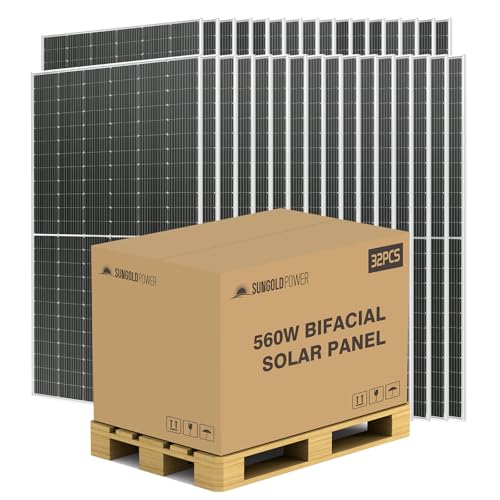
【High Efficiency】 : SUNGOLDPOWER 560W Bifacial monocrystalline PERC solar panel can generate more energy up to 30%
【High Efficiency】 : SUNGOLDPOWER 16BB N-Type 560W Bifacial monocrystalline PERC solar panel can generate more energy up to 30%

★【High Efficiency】 : SUNGOLDPOWER UL61730 CEC Listed N-Type 16BB 590W Bifacial monocrystalline solar panel can generate more energy up to 22.8%. Bifacial technology allows for the harvesting of up to an additional 30% energy from the rear side of the module.
DC‑to‑AC Conversion via the Solar Inverter
Al‑Bsf, PERC, and TOPCon improve rear‑surface carrier collection, which raises cell voltage and fill factor, and that higher output voltage is what the inverter must handle when converting DC to AC. I explain that the inverter receives the panel string’s DC, typically 300‑600 V, and uses high‑frequency switching to reshape it into a 120/240 V AC sine wave, while maintaining a total harmonic distortion below 5 % to meet grid‑tie standards, thereby allowing seamless synchronization with utility voltage and frequency. In a battery‑backup configuration, the inverter also operates in off‑grid mode, drawing DC from a charge controller, then applying a boost‑converter to match battery voltage, usually 48 V, before re‑inverting to AC, ensuring uninterrupted supply during outages. The device’s efficiency, often 96‑98 %, is measured by comparing input DC wattage to output AC wattage.
Recommended Products

【 Save More Bills】Energy is supplied to household loads first, reducing the amount of electricity purchased from the grid, cut grid dependence by 50%+. Compatible with 48V AGM/Sealed, Gel, Flooded, Lithium batteries and a User Mode to work with all battery types.

This Pure Sine Wave Solar Inverter is a combination of an inverter, ac battery charger , MPPT solar charge controller and AC auto-transfer switch. High transfer efficiency is above 85%, built-in AVR stabilizer, complete isolate surge interference of input & output's voltage and current, Impact resistance super load capacity, continuous stable pure sine wave output. Available at 240Vac (HOT1+HOT2) and 120/240Vac output at the same time.

205 Max Amps (up to 50 feet), Rated up to 600 volts, -58°F to +221°F (-50°C to +105°C)
Series vs. Parallel Solar Panel Wiring Explained
How does wiring configuration affect voltage and current distribution across a photovoltaic array, and why must engineers consider both series and parallel connections when designing a system? I explain that in a series string each panel’s voltage adds, so twelve 30‑V modules produce roughly 360 V while the current stays at the panel’s 8 A rating, which raises inverter input voltage but can cause voltage dropout if shading reduces any module’s output; in parallel, voltages remain at 30 V but currents sum, so the same twelve panels yield about 96 A, requiring larger conductors and fuses to prevent overload, and string balancing becomes critical to avoid one underperforming branch limiting overall power. I note that series configurations simplify wiring but increase string length, whereas parallel layouts improve redundancy yet demand careful current management to maintain system efficiency.
Bypass and Blocking Diodes for Shading Management
When panels are wired in series, a single shaded cell can limit the entire string’s current, so engineers add bypass diodes across each cell group to redirect flow around the affected area, allowing the remaining cells to continue delivering power at nearly full voltage. I explain that each bypass diode typically handles 5 A to 10 A, with forward voltage drop around 0.5 V, and that they are placed in parallel with 20‑cell blocks, which limits power loss to less than 5 % under partial shade. Blocking diodes, installed at the string’s output, prevent reverse current when panels are idle, rating usually 30 V and 15 A, ensuring diode reliability during night‑time conditions. Together, these components form a shade mitigation strategy that maintains overall array efficiency, reduces hot‑spot risk, and preserves system longevity without sacrificing output.
Monitoring Solar Panel System Performance and Spotting Losses
Monitoring solar panel performance involves continuously recording voltage, current, and power output, comparing real‑time data against manufacturer‑specified ratings, and detecting deviations that indicate shading, so degradation, or inverter inefficiency; I use performance dashboards that display instantaneous kilowatt‑hour generation, temperature‑compensated voltage curves, and inverter efficiency percentages, allowing me to spot anomalies within seconds, while degradation tracking charts illustrate year‑over‑year output decline, typically 0.5–1 % per annum, enabling precise loss attribution. The system logs each string’s current, flags any string deviating more than 5 % from its baseline, and correlates these events with weather data to differentiate between transient cloud loss and permanent cell wear, thereby ensuring that maintenance decisions rely on quantitative evidence rather than anecdotal observation.
Frequently Asked Questions
How Long Do Solar Panels Typically Last Before Efficiency Drops Significantly?
I’d say panels usually last about 25‑30 years before module degradation cuts output noticeably, and most manufacturers back that with an output warranty guaranteeing around 80 % performance at the 25‑year mark.
Can Solar Panels Generate Electricity on Cloudy or Rainy Days?
I can still produce diffuse generation on cloudy or rainy days, though the spectrum shift reduces intensity, so I’ll generate less power than in full sun, but enough to keep some devices running.
What Safety Measures Protect Against Fire Hazards in Solar Arrays?
I make sure up fire‑safety with diligent array monitoring, rapid shutdown systems, and proper wiring, ensuring isolated circuits, certified components, and clear clear protocols that promptly cut power during emergencies.
Do Solar Panels Affect Roof Structural Integrity or Warranty?
I’ll tell you that panels can add weight, so I usually recommend roof reinforcement; most manufacturers won’t void coverage if the structure meets their load specs, and many warranties even allow warranty transfer to new owners.
How Does Temperature Influence Solar Panel Performance?
I picture a sun‑baked panel, its cells shimmering like a hot skillet; the temperature coefficient drops output, and thermal cycling stresses the material, so hotter days shave efficiency and can wear the panel over time.